2014.12.17
Rayburn Lighting
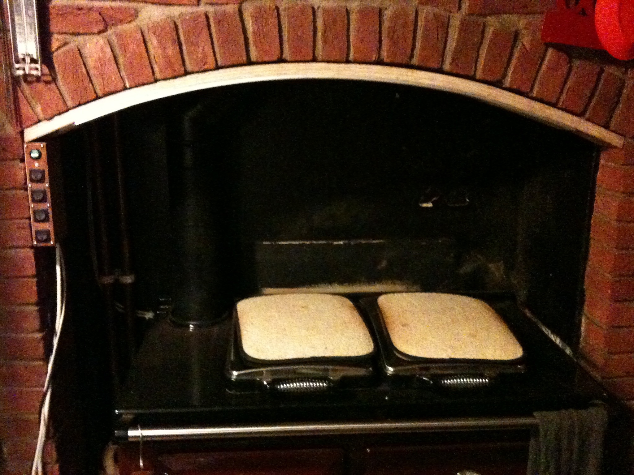
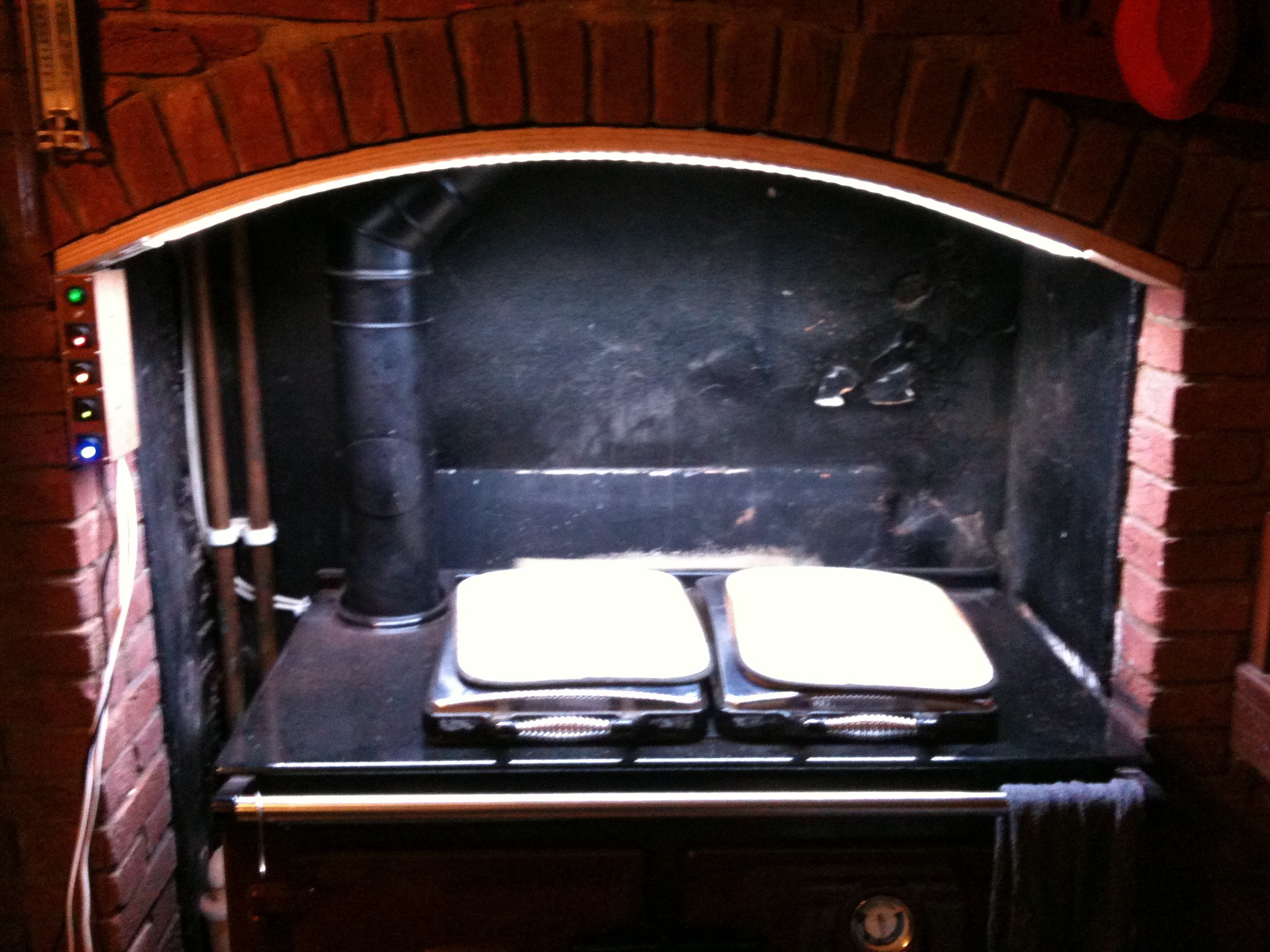
Back in May 2013 shortly after we moved in to our new house, we had a new Rayburn installed, replacing the old, somewhat inefficient, one. It has been great so far but with one slight problem. The range is set in an alcove and in the evenings it can be quite dark there. Winter days can also be a bit dark as well. Needless to say I decided that the best idea would be to install some lighting and the only practical place for this is under the arch of the alcove.
My Number 2 brother works for an architectural company down in Brighton, where he lives, and they deal with lighting a lot, so who best to ask? Having seen the alcove and talked to a few people he recommended LED Tape with a rating of IP67. I didn't know you could get such stuff. Amazing.
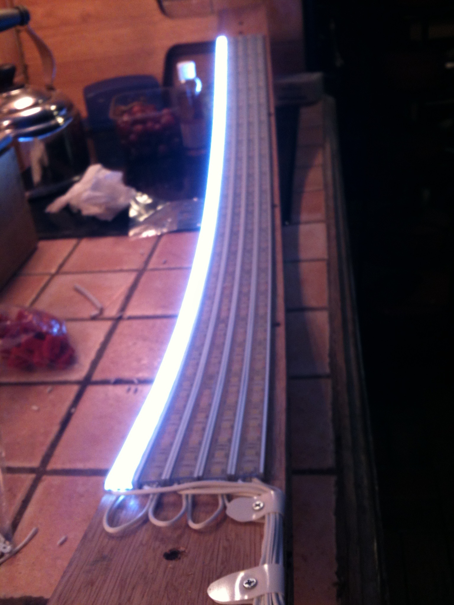
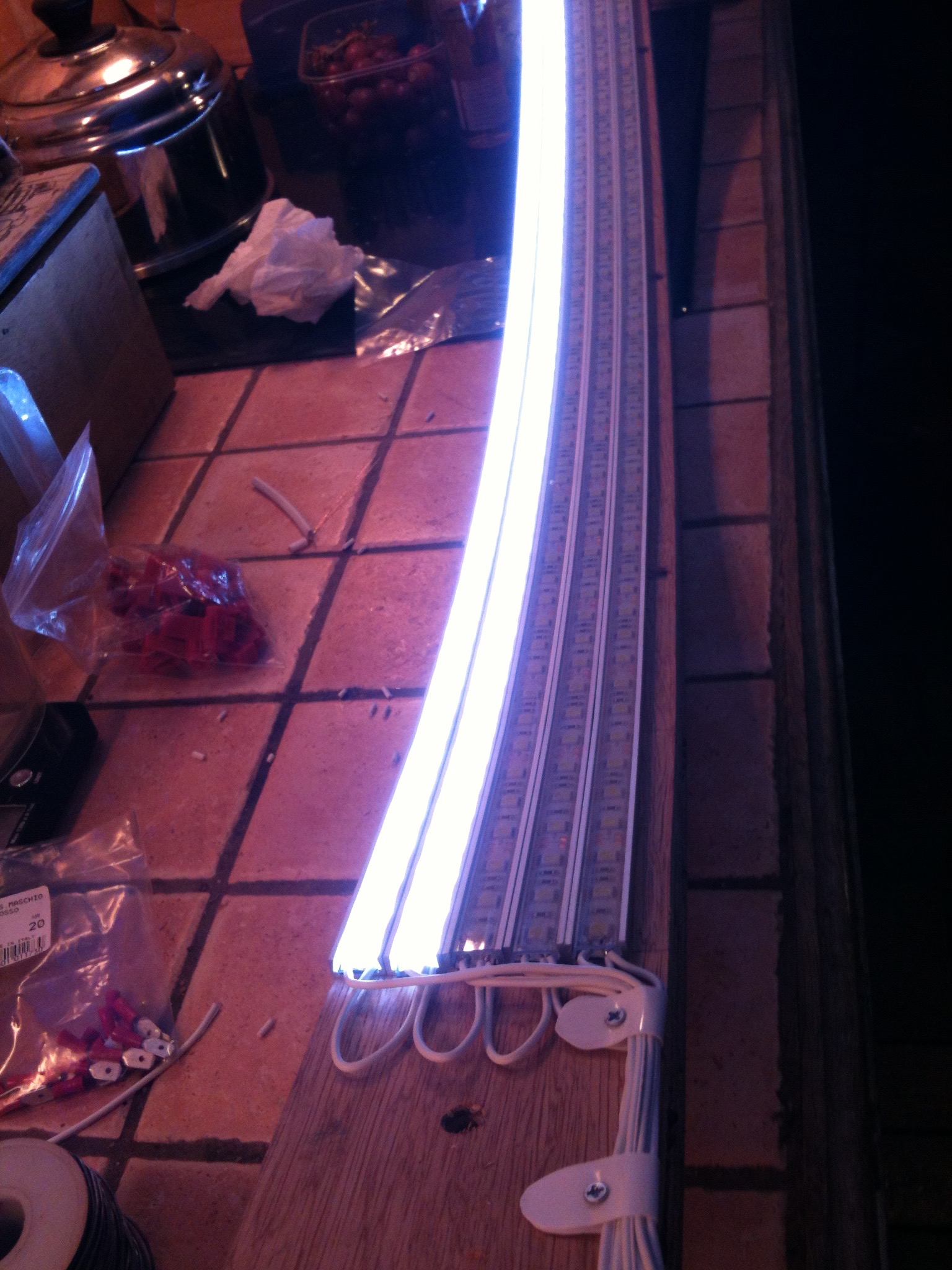
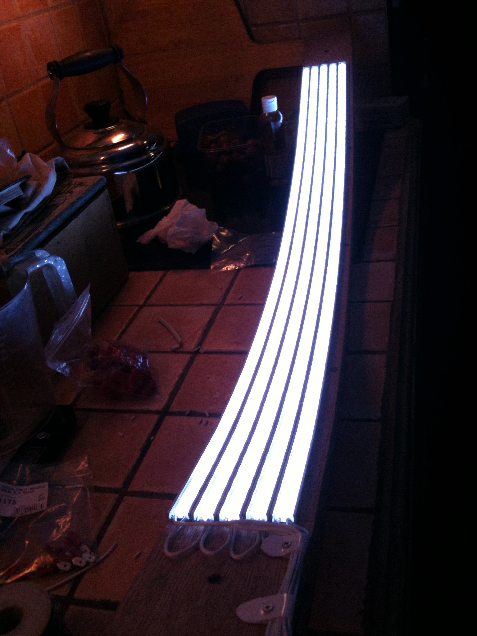
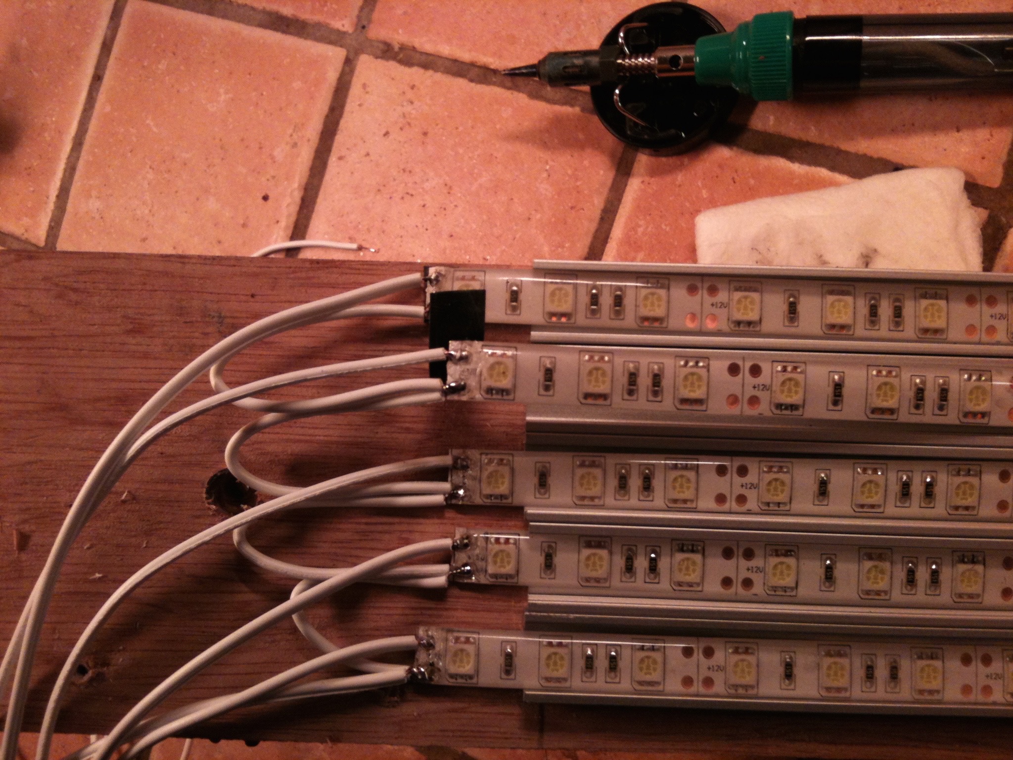
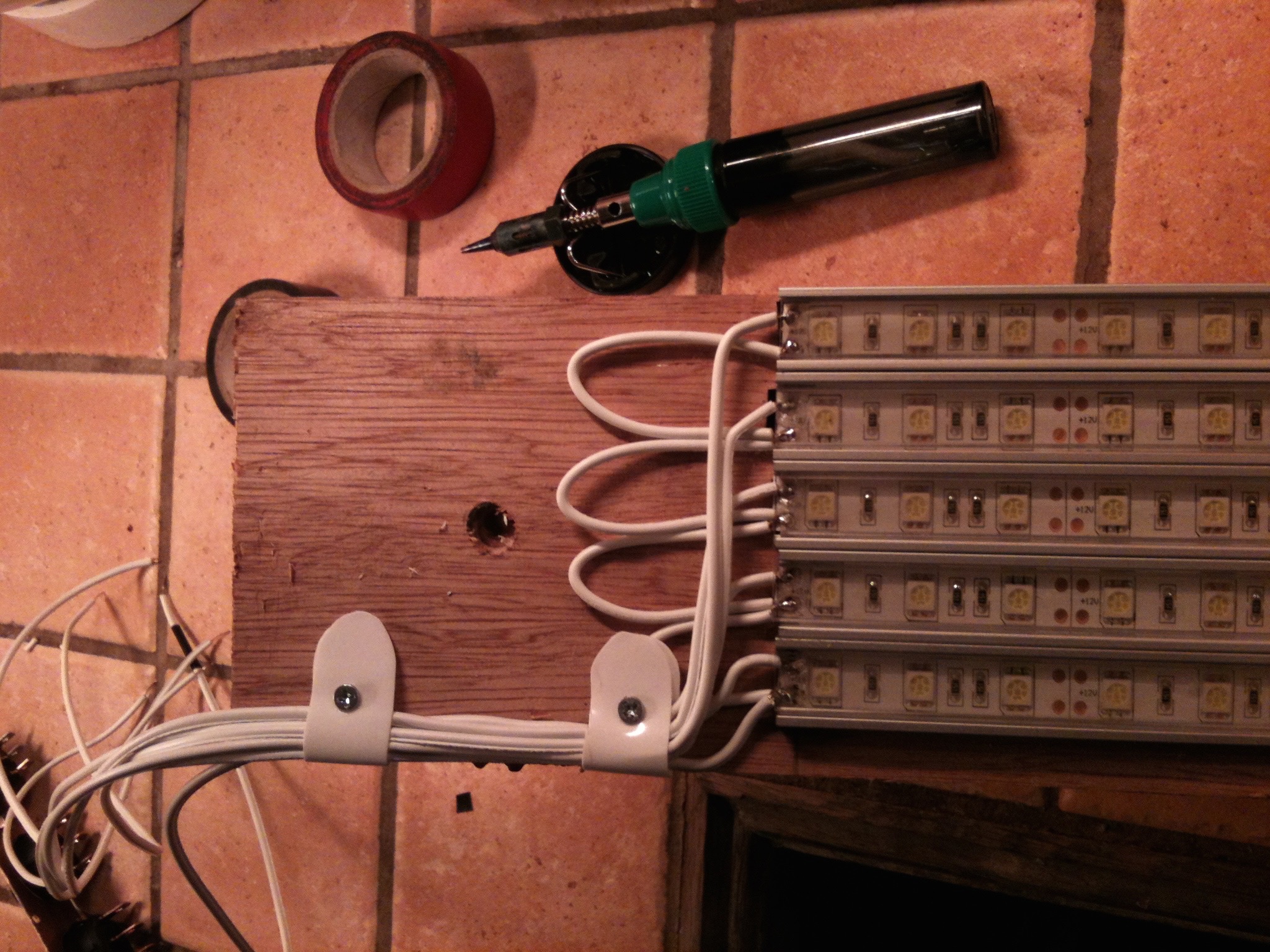
Ebay provided the best price and soon I was the possessor of 5M of LED Tape, five switches (four 12v and one 240v) and five 1M lengths of low-profile aluminium channel made for mounting LED Tape. The LED Tape had 300 surface mounted devices (SMD 5050) that are rated at 390450 lumens per meter, say 400 to make the maths easy.
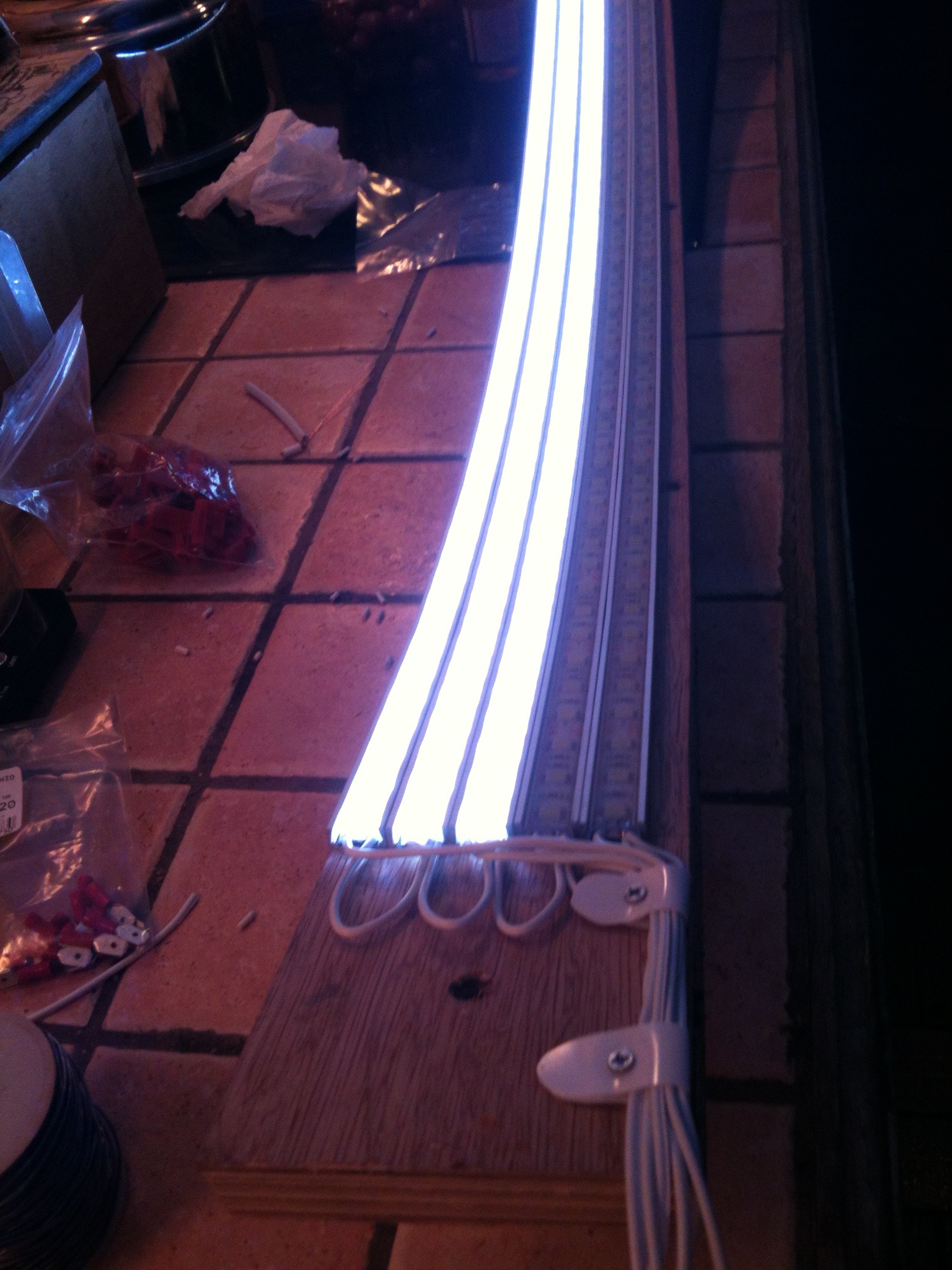
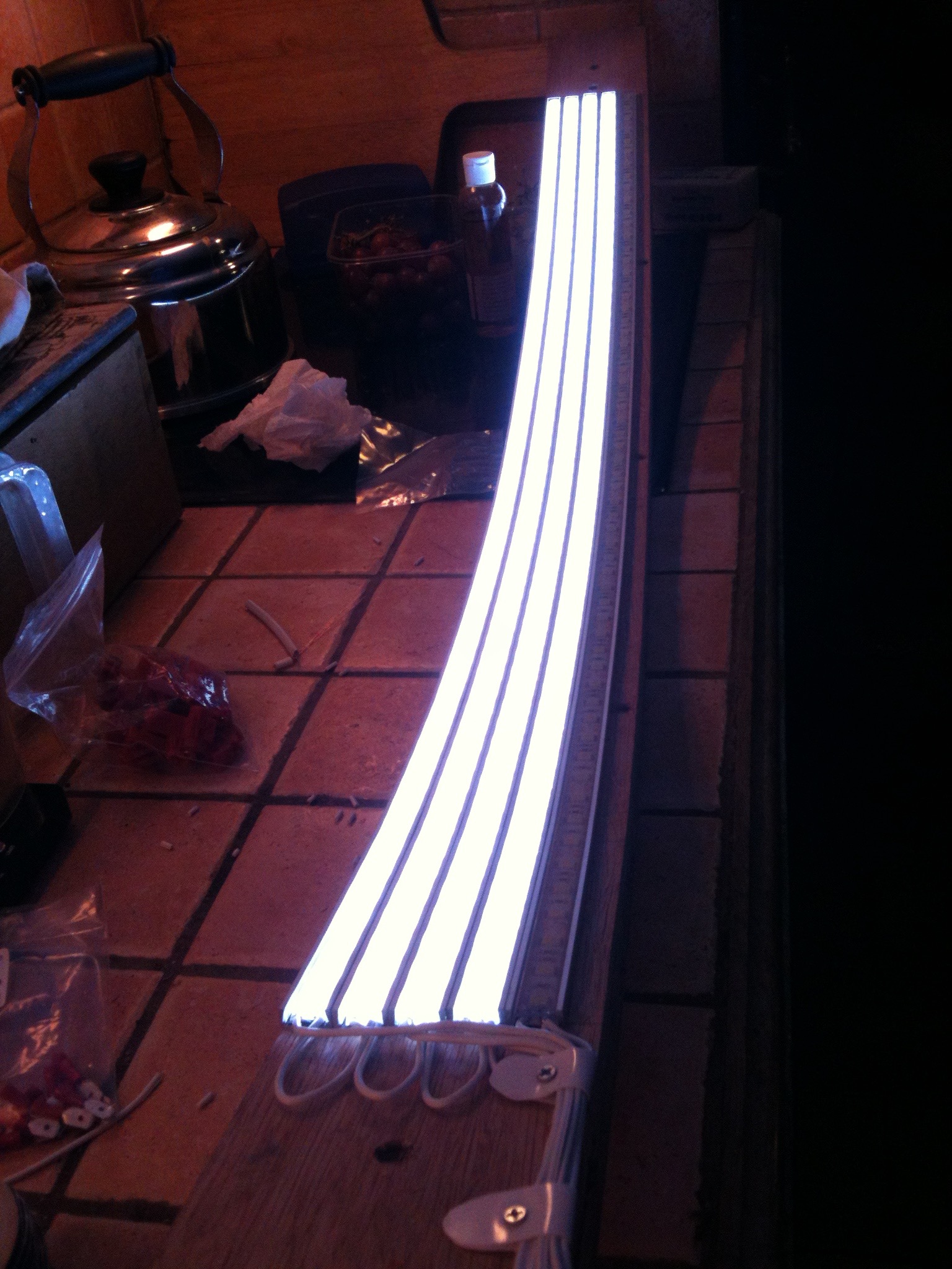
Measuring the arch at 120cm I decided that I would cut the tape in to five 1m lengths and mount each strip in the aluminium channel and use the switches to turn each length on or off giving me five levels of brightness from 400 lumens to 2000 lumens in 400 lumen steps.

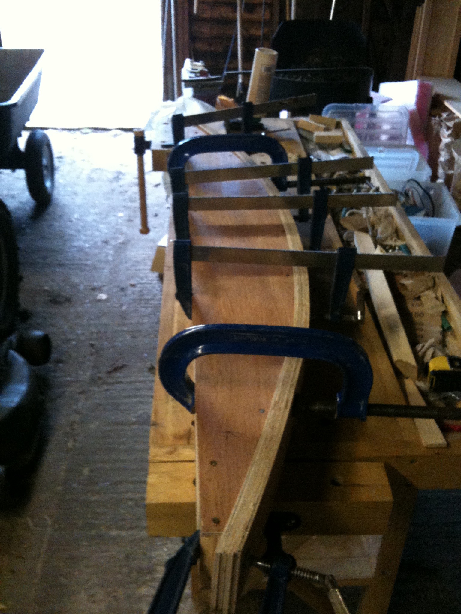
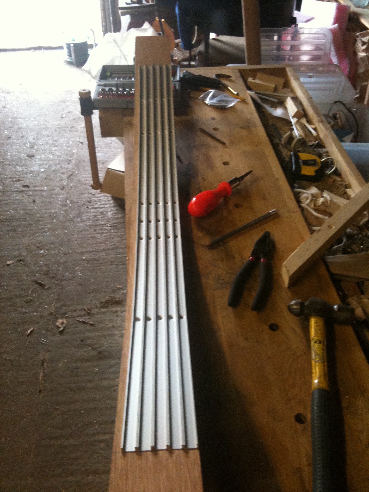
Looking at the arch in detail I realised that a form was needed that would be fixed to the brickwork and allow the aluminium channel to be mounted on the underside. A laminating jig was soon knocked up and I used this to laminate 4 layers of 4mm plywood to give me the former.
Once this was properly dry I trimmed it to length and offered it up to the arch to make sure that is was correct.
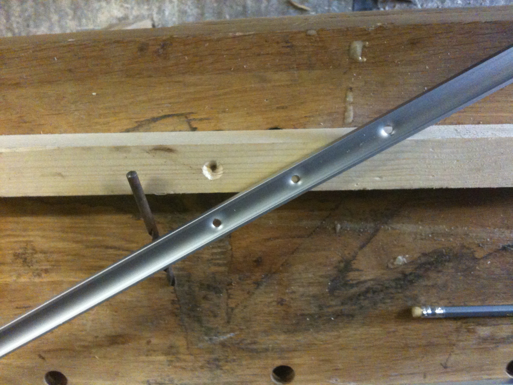
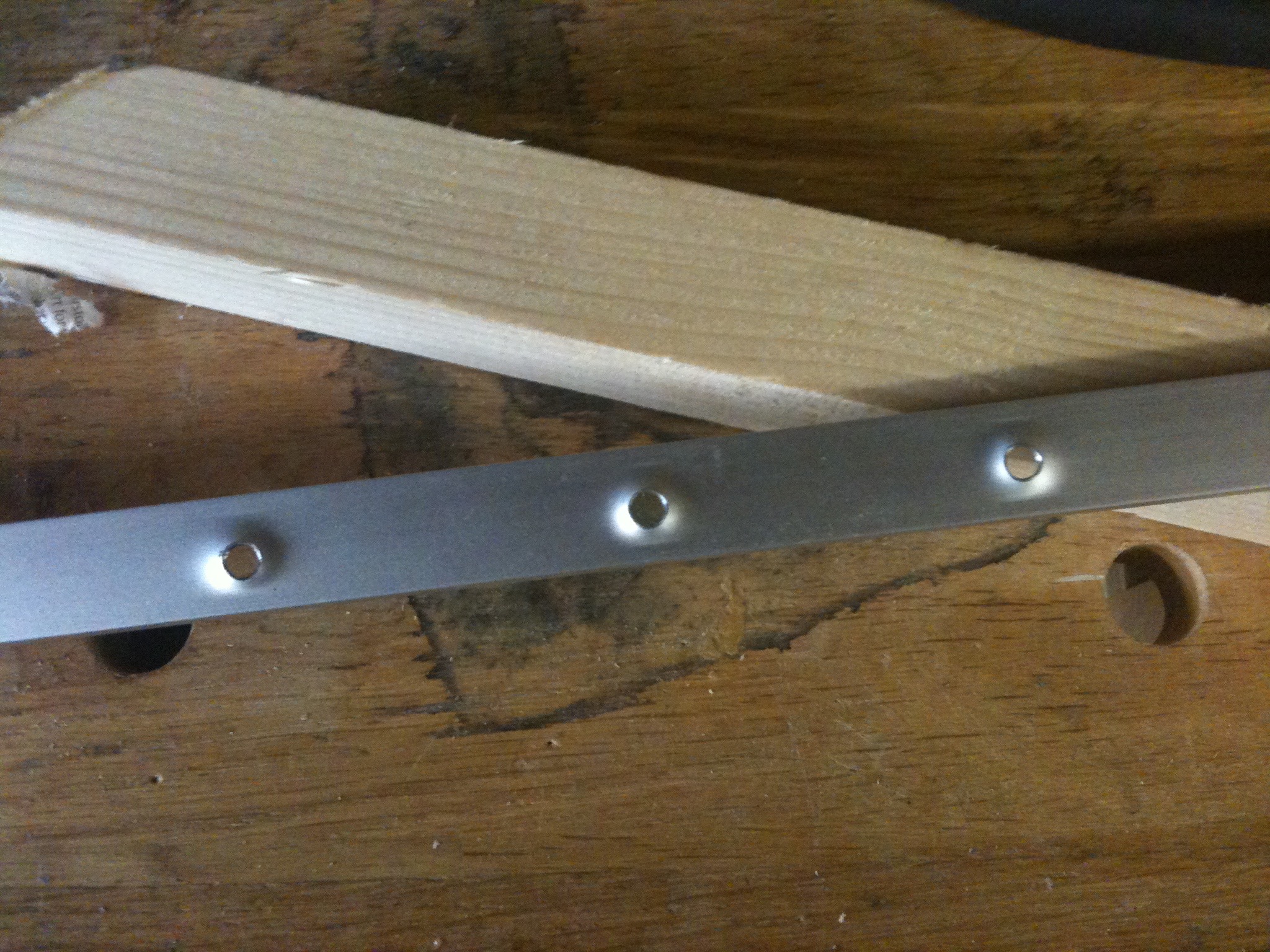
The first photo to the right shows the deforming jig and the second shows the reverse side of the channel showing the deforming more clearly.
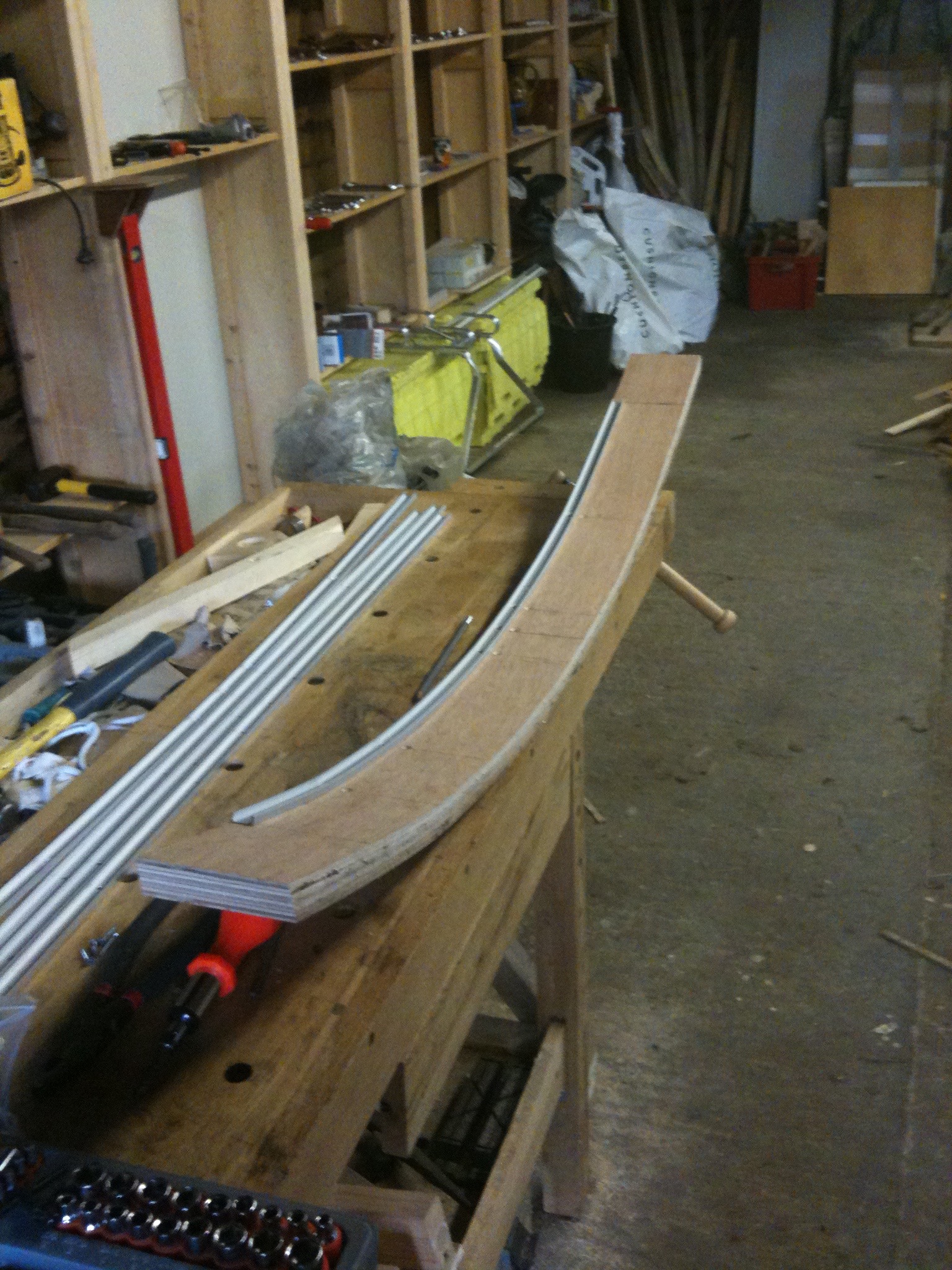
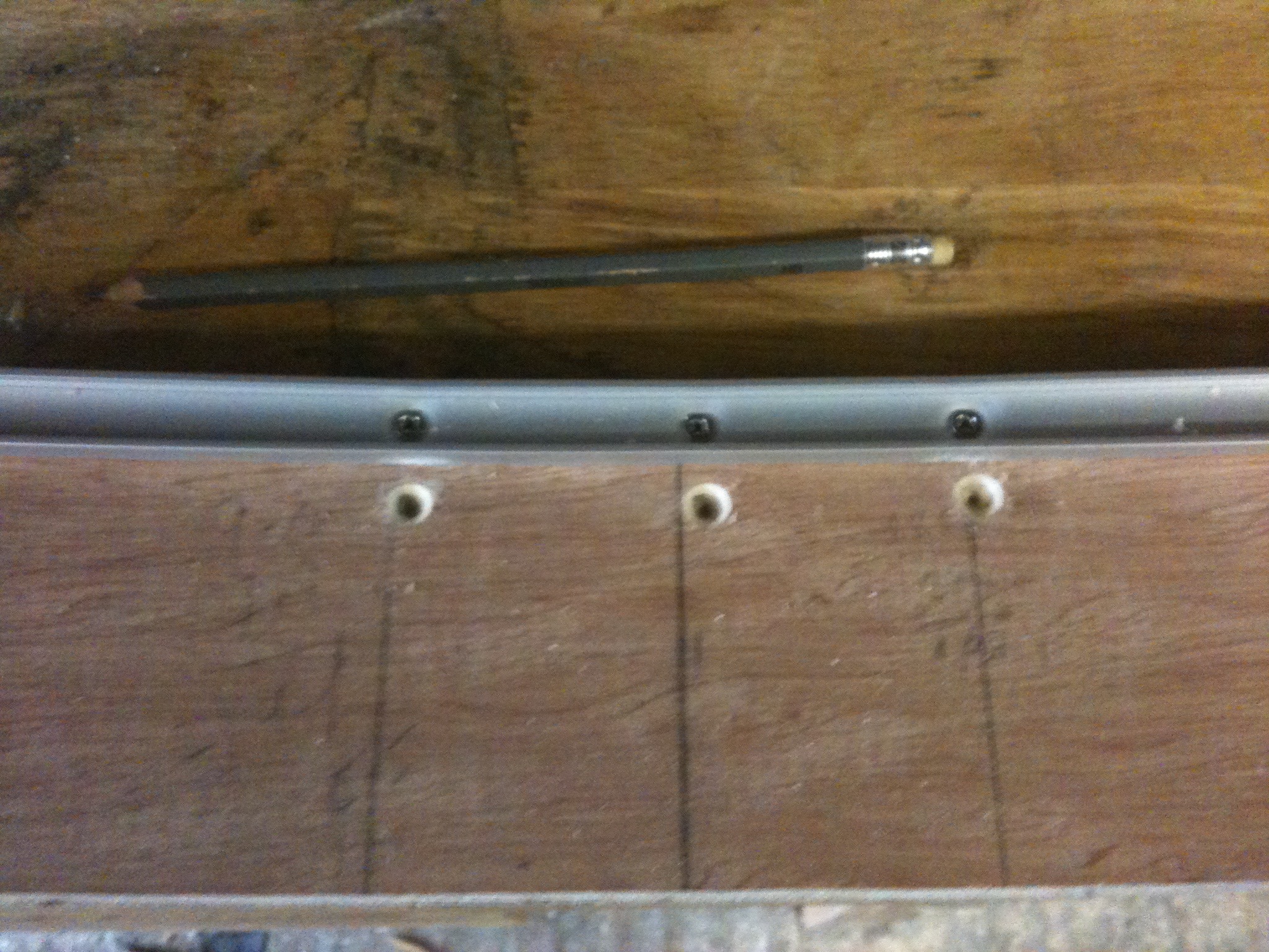
I continued this way until all five channels were fixed to the former.
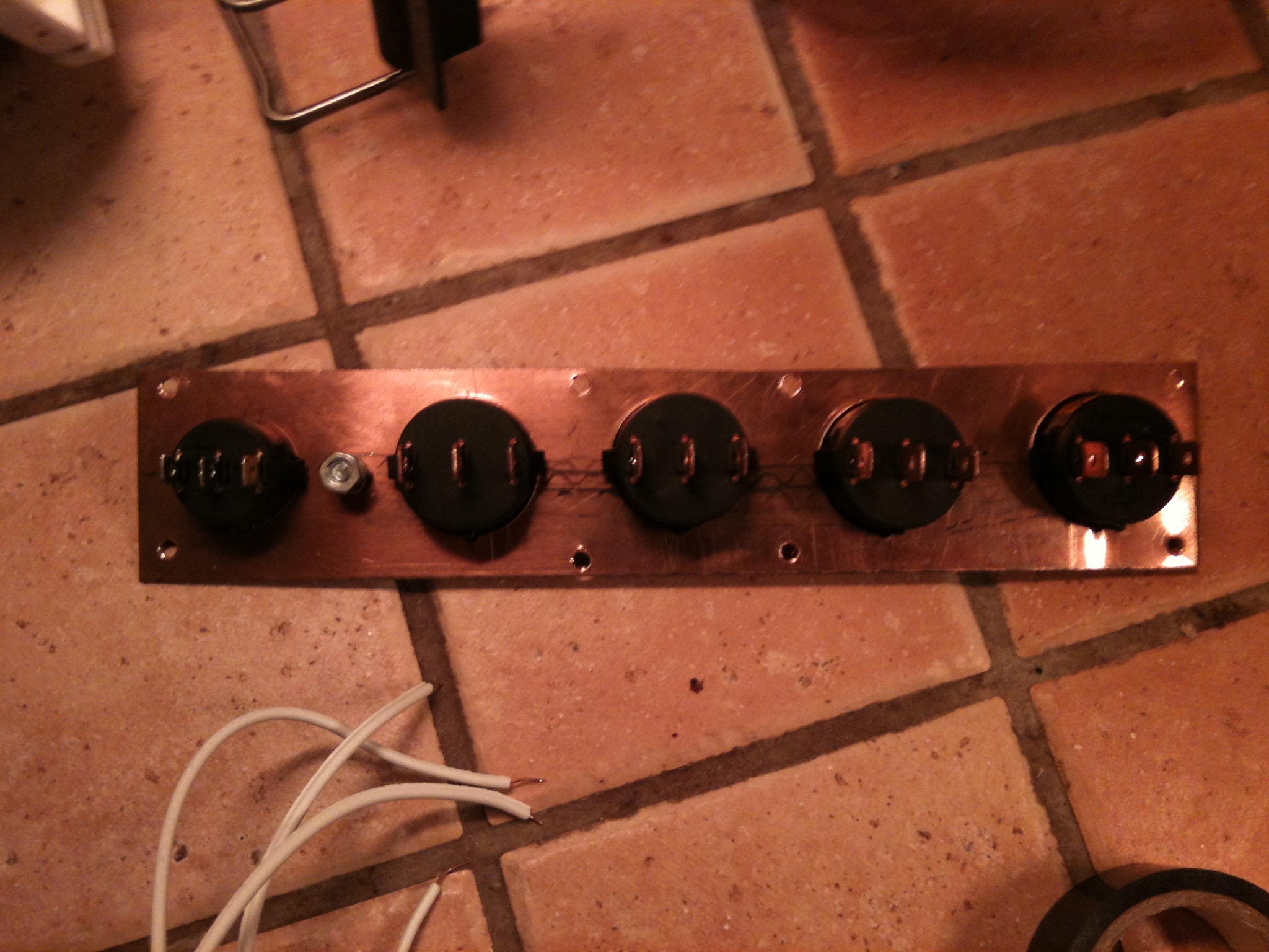
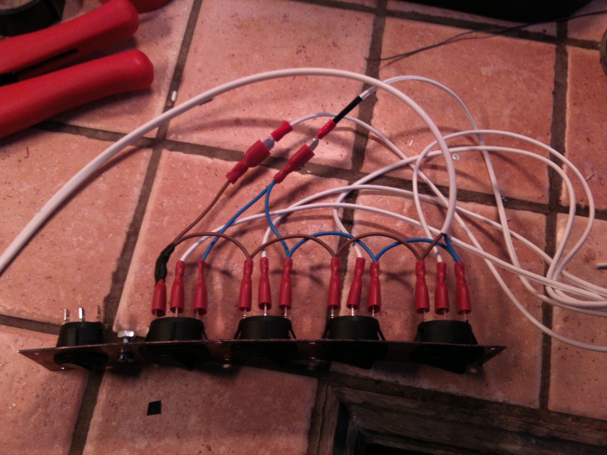
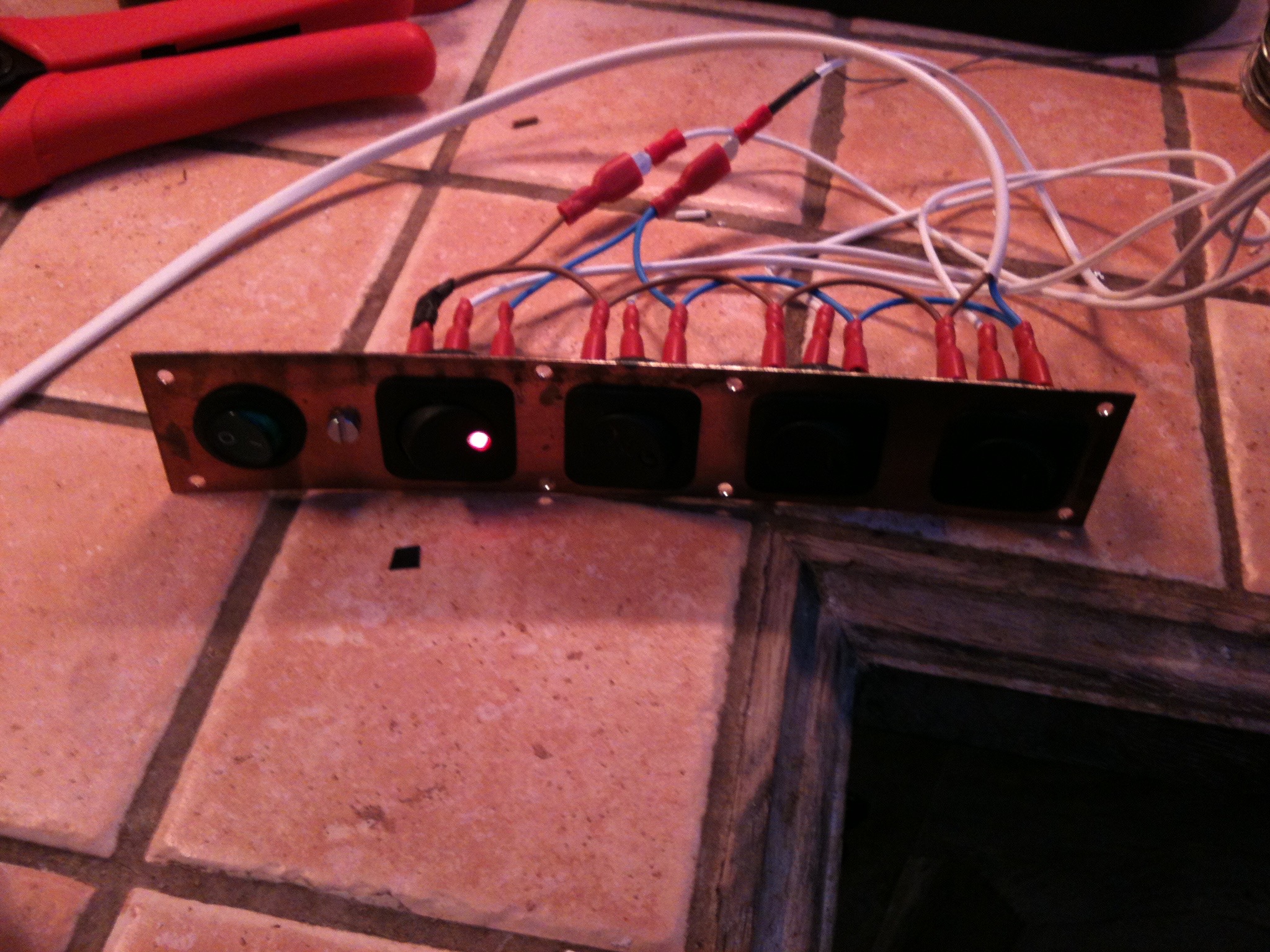
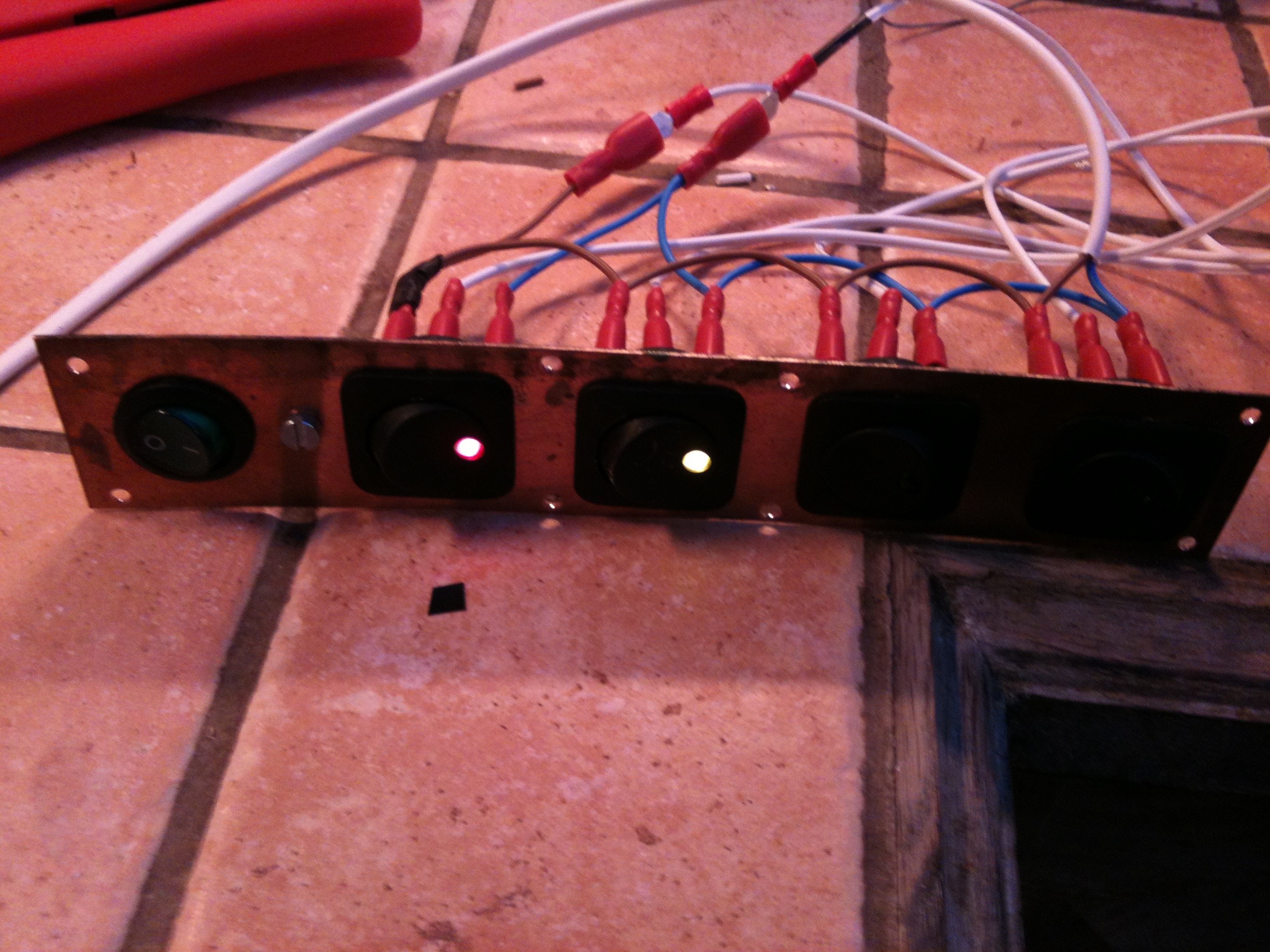
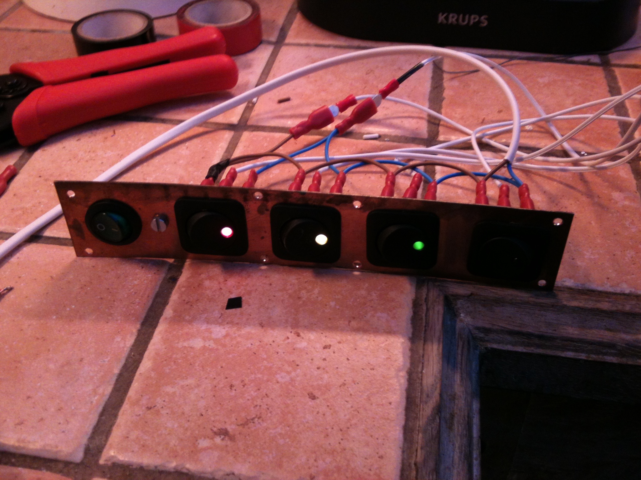
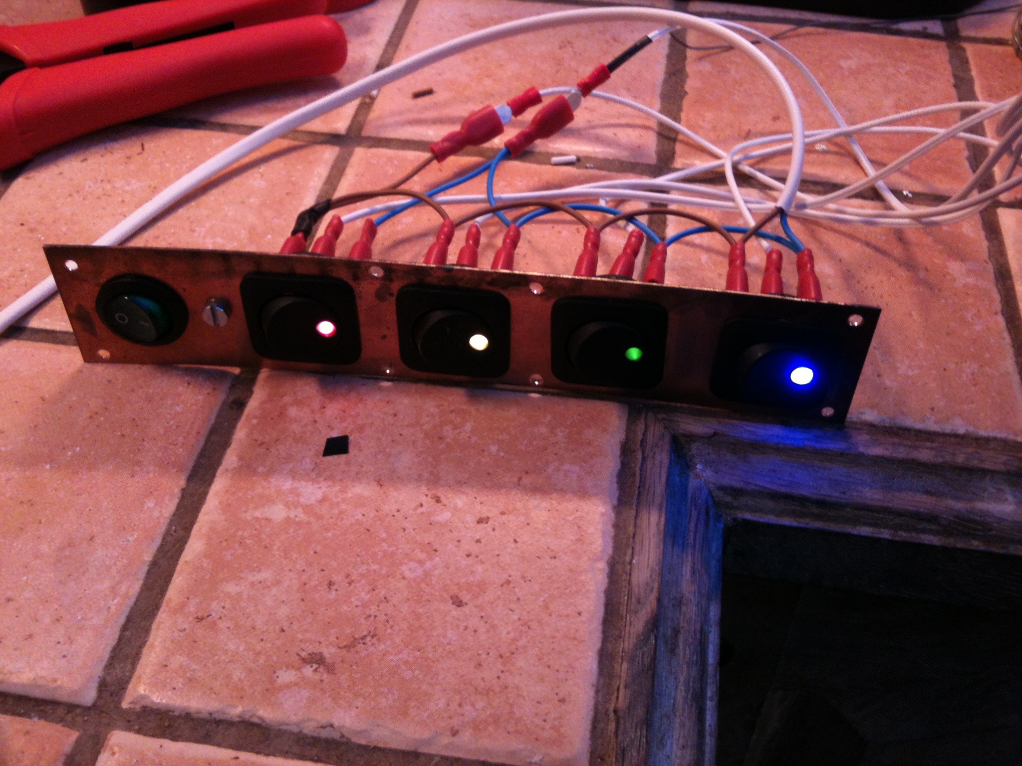
The five switches were mounted on a thin copper sheet with the 240v switch at the top. The intention was that turning on the power to the transformer with the 240v switch would illuminate one strip. The other four 12v switches would be used to turn on the other four strips. as you can see below.